Add Connector
Last update:2023-12-15 18:00:07
Content
1. What is ESA Connector
The ESA connector is a virtual service that is installed in your network to connect your applications and traffic to the ESA platform, enabling organizations to secure communication for cloud workloads over a hybrid network. With the connector, you can benefit from:
1)Protecting your resources without exposing them to the public network;
2)Simplifying traffic forwarding to the ESA platform through an encrypted tunnel established between the connector and the security gateway;
3)Seamless connectivity between private or cloud applications and the Internet.
2. Understand Connector
1)Connectors are distinct from VPN gateways and should not be accessed by users on the public network. Users should connect to the VPN server component on the security gateway, not the connectors;
2)Connectors are deployed to securely connect applications to the ESA service;
3)Connectors create secure tunnels with the security gateway to safeguard data and resources;
4)Deploy connectors in each site where your applications are located;
5)The ESA connector is provided at no cost, allowing you to deploy as many as needed.
3. Preparations for Deploying Connector
1)VM requirement
When determining the VM specifications for the connector, consider:
- The number of concurrent users connecting to the connector
- Bandwidth requirements for each user
- Memory and CPU resources
- Currently, the ESA connector can only be installed on Centos 7.x. Support for other systems or Docker installation is planned for next year.
For typical office scenarios, users typically do not require high bandwidth for access. Our recommendation is to add another connector or migrate to a higher-capability VM if the connector’s capacity becomes strained. Migration is a straightforward process.
| Bandwidth | User Account | Server capability requested |
|---|---|---|
| 15Mbps |
100 users |
1 core CPU@3.00GHz,2GMemory,50G disk,able to connect to public network |
| 50Mbps | 500 users | 2 core CPU@3.00GHz,4GMemory,50G disk,able to connect to public network |
| 100Mbps | 1000 users | 8 core CPU@3.00GHz, 16GMemory, 100G disk, able to connect to public network |
2)Where to locate connector
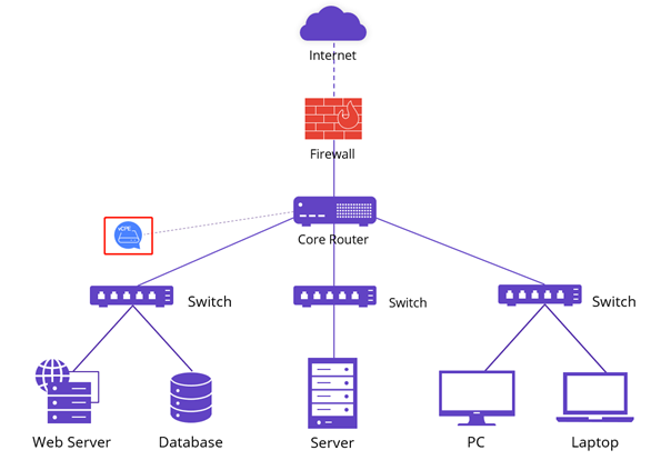
Install the connector in the environment where your resources are located. If you have multiple sites or clouds, install one connector in each site. One connector can be used to connect multiple applications.
For instance, in a network like the one depicted below, the connector can be installed on a server under the core router, allowing the core router to forward essential traffic to the connector. If you have a complex infrastructure and are unsure where to place the connector, please send your network topology to our engineers for guidance.
3) Network Requirement
- Ensure that connectors have access to the public network to communicate with ESA security gateways.
- Verify that the connector can communicate with your applications.
- If your router or firewall has network traffic control, ensure that the connector’s WAN IP can access the Internet and allow the below ports for data transfer (allowing the traffic is sufficient; port mapping is not required).
| Traffic Direction | Protocol | Port |
|---|---|---|
| Outflow |
UDP | 500 600 4500 4600 8899 8900 8901 8902 53 123 |
| Outflow |
TCP |
80 443 6001 6002 6011 6012 7002 7003 7004 9900 |
| Inflow |
UDP |
500 600 4500 4600 8899 8900 8901 8902 |
4.1 Deploy Single Connector
1)Add new connector
Go to Application Deployment–>Connector, click Add, and choose Software Version (Hardware version only available for specific regions)

2)Configure Basic Info
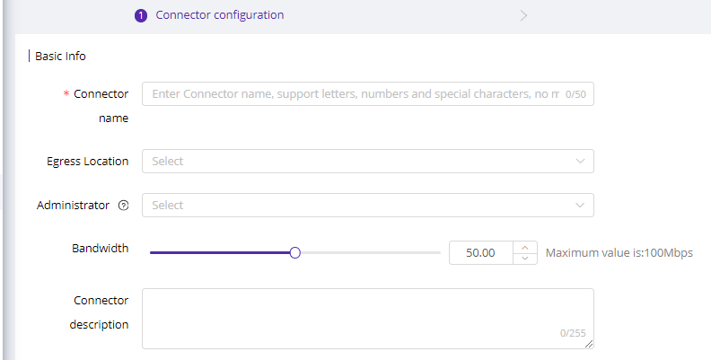
Here are parameter explanations:
| Field Name | Explanation |
|---|---|
| Connector Name |
1-50 characters, support letters, symbols and numbers. |
| Egress Location | Choose the geolocation of your VM. With the egress selected, platform will connect it to latest edge. |
| Administrator | Choose the administrator of this connector for easy identification. Or just leave it blank. |
| Bandwidth | Select bandwidth based on your egress bandwidth and business need. |
| Connector Description | 1-255 characters, used to describe the connector for easy identification and management. |
3)Configure SNAT
Client Virtual IP Range: During the initial setup, our engineer will assist in configuring a client virtual IP range. This range is used to assign IPs to ESA clients when users log into their accounts. The client virtual IPs will be used to communicate with the security gateway and should not conflict with your current network. If you need to change it, please go to System Settings->Common Settings
![[Feature Upgrade] Advanced Access Control](https://documents.cdnetworks.com/wcs/draft/help_doc/zh_cn/24246/30021/1702619862479_image.png)
Source Address Translation (SNAT) is used to conceal the actual IP of the source application.
- Disable: If the client virtual IP can directly communicate with applications, please disable SNAT.
- Enable: If the client virtual IP cannot directly communicate with applications, you need to enable SNAT. Once enabled, clients will connect to the connector’s IP, and the connector will forward traffic to the application. However, in the user behavior audit log, you will only see users connecting to the connector.
Alternatively, if the client virtual IP cannot communicate with the application and you want a clear user behavior audit, do the following:
- Disable SNAT
- On your router or switch, create a route from the user client IP range to the application.
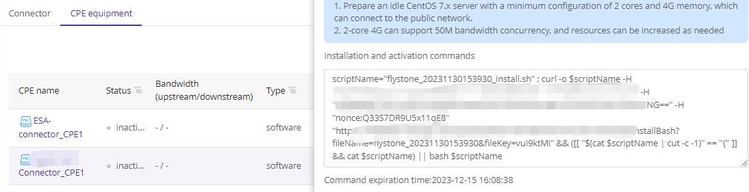
Click Submit to generate the connector installation string.
4)Copy string and install on your server
- Click the string box to copy installation string

- Login to your VM with Root permission, execute the string
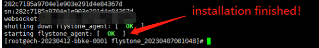
Server will download the connector installation packet from our platform and start installation. Make sure your server can connect to public network.

The two green OK is the symbol of success installation.
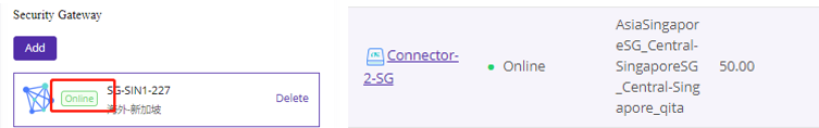
5)Deploy to security gateway
After installing the connector, navigate to the Connector list and click Manage. Select a security gateway from the list to deploy the connector to the platform.

Once the gateway status changes to Online, return to the Connector list to verify that the connector is also Online. This completes the successful deployment of a CPE.
Repeat steps to add connectors on other sites.
4.2 Deploy connector redundancy
1)How it works
The redundancy of the ESA connector relies on the VRRP Protocol. It’s important to understand that the hot standby mode does not enable load balancing; its purpose is solely to ensure high availability. In a VRRP infrastructure, multiple connectors form a virtual group and operate as a unified entity. Redundancy is achieved within this virtual group, which utilizes a virtual IP for communication with other devices. To set up connector redundancy, you will need to prepare two VMs and one virtual IP, all of which should be in the same subnet.
2)Installation steps
-
Step 1/2 is same like deploy single connector
-
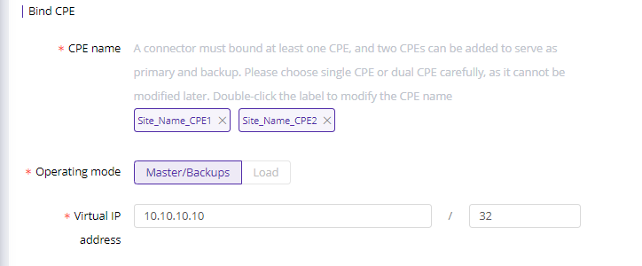
Bind CPE
Click Add to add a second CPE and enter virtual IP. Currently we only support master/backup mode for high availability.
-
Copy installation for each connector and install on your VMs

-
Rest of the steps are same like deploying single connector.
Please note the installation string is effective for only 60 minutes. If it expires, please go to the CPE equipment and click on Manage to obtain a new string.